Future-proof your structured cabling system
with a fiber optic loss budget
The design of a fiber optic system is a balancing act. As with any system, having set criteria for performance is important, with checks in place to determine how to meet those criteria. It's important to remember that we are talking about a system that is the sum of its parts. Calculation of a system's capability to perform is based upon a list of elements that are crucial in order to ensure success in the longevity of a fiber optic cabling system. Following are several elements to consider:
A calculated fiber optic power and loss budget
The loss budget is the basic blueprint from which a fiber optic system route can be designed and is crucial for success. The loss budget refers to the amount of loss that a cable plant should have if it is installed properly and is calculated by adding the estimated average losses of all components used in the cable plant to get the estimated total end-to-end loss.
The loss has two uses 1) during the design stage it is used to ensure the cabling being designed will work with the links intended to be used over it and 2) after installation the loss budget for the cabling is compared to the actual test results to ensure the cable plant is installed properly.
Link loss budgets are measured based on the amount of attenuation, or signal reduction, related to the distance and number of connectors in a fiber optic link. Prior to designing or installing a link, the path and connections should be calculated for maximum or worst-case loss.
Some factors that can affect the link include: The design of the fiber optic cables/cabling infrastructure/stressing the cable; absorption, scattering, or impurities in the glass; distance from end to end of the link; the number of connectors, splices, and coupler systems in a link; degradation in the transceivers/active components; inferior product design; end-face contamination; aging passive components and exceeding bend radii.
Future-proofing your cabling infrastructure
As mentioned above, it is crucial for the success of your fiber optic system to future-proof it by performing a link loss budget analysis of the components that make up the end-to-end fiber optic links in the system.
It is recommended that when conducting this link loss budget analysis, to be conservative. The various link loss budget specs from Ethernet, Fiber Channel and InfiniBand are readily available and provide maximum loss figures (see Figure 1 below). It is best practice to design the link out to only 70% of the maximum loss budget stated. This approach will help ensure the connected equipment will work over the installed fiber optic link.
Industry standards
Acceptable fiber optic link loss budgets are defined by the various published speed standards from groups like the Institute of Electrical and Electronics Engineers (IEEE) and the Fiber Channel Industry Association (FCIA). These two standards address speeds from 1Gb to 400Gb for Ethernet and 4Gb to 128Gb Fiber Channel.
New standards are being introduced at a fast rate. The IEEE 802.3ba standard and its updated version, IEEE 802.3bm, introduced 100G Ethernet into the data center space over a decade ago. The next IEEE Ethernet standard, 802.3cd, addressed supporting speeds of 50/100/200Gb. Soon after arrived 802.3bs, which addressed speeds of 200Gb and 400Gb Ethernet. In 2018, Fiber Channel went from Generation 6 to Generation 7, with 64Gb speeds on duplex connections to 256Gb on parallel connections. The need to support higher speeds has already arrived.
Figure 1 below indicates specified link loss budgets for Ethernet and Fiber Channel at various speeds:
Application | Standard | Fiber | Rated reach | Max. channel loss | Connection loss |
|---|---|---|---|---|---|
10-Gigabit Ethernet | 10GBASE-SR | MM OM4 | 400 m | 2.9 dB | 1.5 dB
|
25-Gigabit Ethernet | 25GBASE-SR | MM OM4 | 100 m | 1.9 dB | 1.5 dB
|
40-Gigabit Ethernet | 40GBASE-SR | MM OM4 | 150 m | 1.5 dB | 1.0 dB
|
50-Gigabit Ethernet | 50GBASE-SR | MM OM4 | 100 m | 1.9 dB | 1.5 dB
|
100-Gigabit Ethernet | 100GBASE-SR | MM OM4 | 1500 m | 1.5 dB | 1.0 dB
|
200-Gigabit Ethernet | 200GBASE-SR | MM OM4 | 100 m | 1.9 dB | 1.5 dB
|
400-Gigabit Ethernet | 400GBASE-SR | MM OM4 | 100 m | 1.9 dB | 1.5 dB
|
32G Fiber Channel | 32GFC | MM OM4 | 100 m | 1.86 dB | 1.5 dB
|
128 Fiber Channel | 128GFC | MM OM4 | 85 m | 1.9 dB | 1.5 dB
|
Figure 1
The build-out and port replication guidelines published in the TIA-942-B data center topology standard will create a structured cabling solution. This standard serves as a baseline for anyone who wishes to design and build a reliable and efficient data center. To meet the need of this standard, the system must have interconnects, which are critical to managing the high port density requirements of today's data centers. It is recommended to eliminate any contributing factors that would introduce loss into a link that isn't native to the installed fiber optic cabling plant or its connectors, splices, or any of the components. Even small loss points of 0.1 and 0.2dB add up very quickly.
Industry standards for interconnect loss (TIA-568), state the LC connector has a standard of 0.5dB per mated pair, and the MPO has 0.75dB per mated pair. If a basic link of two MPO-LC cassette modules between an MPO to MPO fiber optic trunk occur, the maximum dB loss will equate to -2.5db. This is 1dB over the specification for interconnects in the link to support 100G. I's easy to see how it doesn't take many interconnects to significantly be at or above the 40Gb spectrum minimum loss requirements, without the hope of ever achieving 400Gb (see Figure 1).
Interconnect loss
The loss budgets are very small at 2.6 dB total link loss for 10Gb Ethernet and 8Gb for Fiber Channel. These losses drop to 1.9dB total link loss with a connector loss of 1.5dB to 1.0dB as you progress up the spectrum to 256Gb Fiber Channel and 400 Gb Ethernet.
These higher speeds leave very little margin for error in fiber optic infrastructure components, and insertion loss is a critical performance parameter in data center cabling measurements. Total connecter loss and the overall loss budget is taxing the data center to operate error-free and perform over supportable distances. The supportable distance for these new high-speed requirements for Ethernet and Fiber Channel is shrinking to between 100 meters and 150 meters on multimode fiber. Most data center links won't exceed this distance.
According to the TIA-568 standard, the attenuation of OM4 at 850nm is 3.5 dB/KM. Therefore the estimated standard loss is 0.4dB per the distance spec of the link. This distance loss can be further tuned in extenuating circumstances if the link is shorter than the maximum standard, giving us more room within the link loss budget for speed.
Creating the design of the link
When creating the design of the link, research is critical. The standard loss ratings assigned to the components needed should not alone be the final guideline for product selection. Standards offer a minimum recommended requirement for performance and a starting point reference. To ensure a design that leaves headroom in the link budget, products should be used that exceed these industry standards.
A cable will go through multiple build steps and checkpoints before being terminated, yet even in the final test, if performance doesn't meet expectations there is little that can be done. Most of this 'defective' subset will need to have the connector removed and the process started again. Allowing for higher dB loss will mean less waste and lower costs. Higher expectations increase the cost for better-performing products.
Look for companies that offer quality products with low dB loss and documentation to verify these performance results. Locate products that offer 0.15-0.25dB for LC and 0.20-0.35 for MPO per mated pair. You will be able to deploy a manageable fiber infrastructure that will last the next 10 to 15 years and significantly exceed industry standards.
How to estimate a link loss budget
The first step is to find the allowed link loss budget per speed of transmit (using Figure 1 above) and calculate the typical expected total link loss from the length of the fiber optic link. Then add up all of the interconnects. Splices will need to be calculated as well, but they are highly unusual in a data center.
Figure 2 below gives an estimated calculation of what the link loss budget could be. When implementing this link at the speed required in a real-world scenario, there are other considerations relating to loss that can improve actual performance:
Cabling link loss | Description | TIA-568 maximum loss | |
|---|---|---|---|
Cable attenuation | Multimode OM4, 850nm | 3.0dB/km | |
Connector mated pair | LC/MPO | 0.50dB / 0.75dB | |
Splice | Fusion/mechanical | 0.10dB / 0.20dB |
Other considerations relating to loss that can improve performance include: Quality components manufactured for performance and reliability; best practices installation of the infrastructure design maintaining proper bend radii and efficient cable routing; inspection of the fiber end faces and cleaning as necessary prior to installation; plan an acceptable dB buffer into the calculation and transceiver effectiveness.
Loss budget allowances for network/SAN/InfiniBand equipment may depend on the difference between the sensitivity of the receiver and the output of the transceiver into the fiber. Over time, the degradation of the sources or transceiver is a factor that many forget or aren't aware of. Make sure there is ample head room in the link loss budget and design to a maximum of 70% of the standard link budget.
Degradation in the quality of fiber optic connectors and splice terminations in the infrastructure may also occur over time. Some field-installable connectors and mechanical splices wear, and the index matching gel degrades, which can contribute to higher losses.
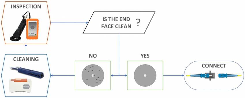
Even if best practices are followed, connectors can get dirty or contaminated. With a fiber diameter of less than a human hair, contamination is not easily avoided. Consider data centers in very low humidity locations where static charges on connector ferrules attract particles and dirt, even after cleaning.
Figure 3 to the right shows best practices for fiber optic end face cleaning.
Figure 3
Conclusion
Consideration of all the factors involved in contributing to loss, or the elimination of loss, will ultimately allow you to build a fiber optic structured cabling system according to the TIA-942 standards and be comfortably under the 400G loss budget requirement. Mix in better-performing manufactured components, staying well within the maximum cabling distance calculated for the link at a set speed, and apply "worst-case maximum values" during loss calculations, and a data center infrastructure will last for generations.


