


A well-designed network rack is far more than a tidy enclosure for switches, patch panels and power equipment. It is the physical foundation of a reliable network—supporting consistent performance, easier maintenance, safer power distribution and straightforward future expansion.
Whether you are fitting out a compact communications cabinet, a school or office network room, or a larger enterprise installation, taking time to plan the rack layout before equipment is mounted can prevent many of the issues that later lead to downtime, overheating and difficult troubleshooting.
Start with a Complete Plan
The most effective rack layouts begin on paper—or in a rack-design tool—rather than at the installation stage. Create an inventory of every item that will live in the rack, including its rack-unit height (U), depth, weight, power requirements, heat output and port count.
This should include:
- Patch panels and cable-management panels
- Network switches, including PoE or PoE++ models
- Routers, firewalls and network video recorders
- Servers, storage devices and controllers
- Uninterruptible power supplies (UPSs) and power distribution units (PDUs)
- Fiber enclosures, splice trays and media converters
- Shelves for non-rack mount equipment
- Cooling equipment, blanking panels and environmental monitoring hardware
A standard rack is measured in rack units, where 1U equals 44.45 mm in height. Count the required U-space, then deliberately allow capacity for change. A practical rule is to retain around 20–30% spare space for additional network equipment, patching, cable management and airflow. Planning a rack to be completely full on day one can make even a modest upgrade unnecessarily disruptive.
Build a Logical Equipment Order
A consistent top-to-bottom layout makes installations easier to understand, service and document.
The exact arrangement will depend on the equipment, cabling pathways and cooling design, but the principle is simple: keep closely connected equipment close together, keep heavy equipment low, and preserve clear airflow.
Where patching density is high, a “patch panel → cable manager → switch” sequence is particularly useful. It shortens patch-cord runs, prevents cable congestion at switch ports and gives technicians a clearer path when tracing or replacing connections.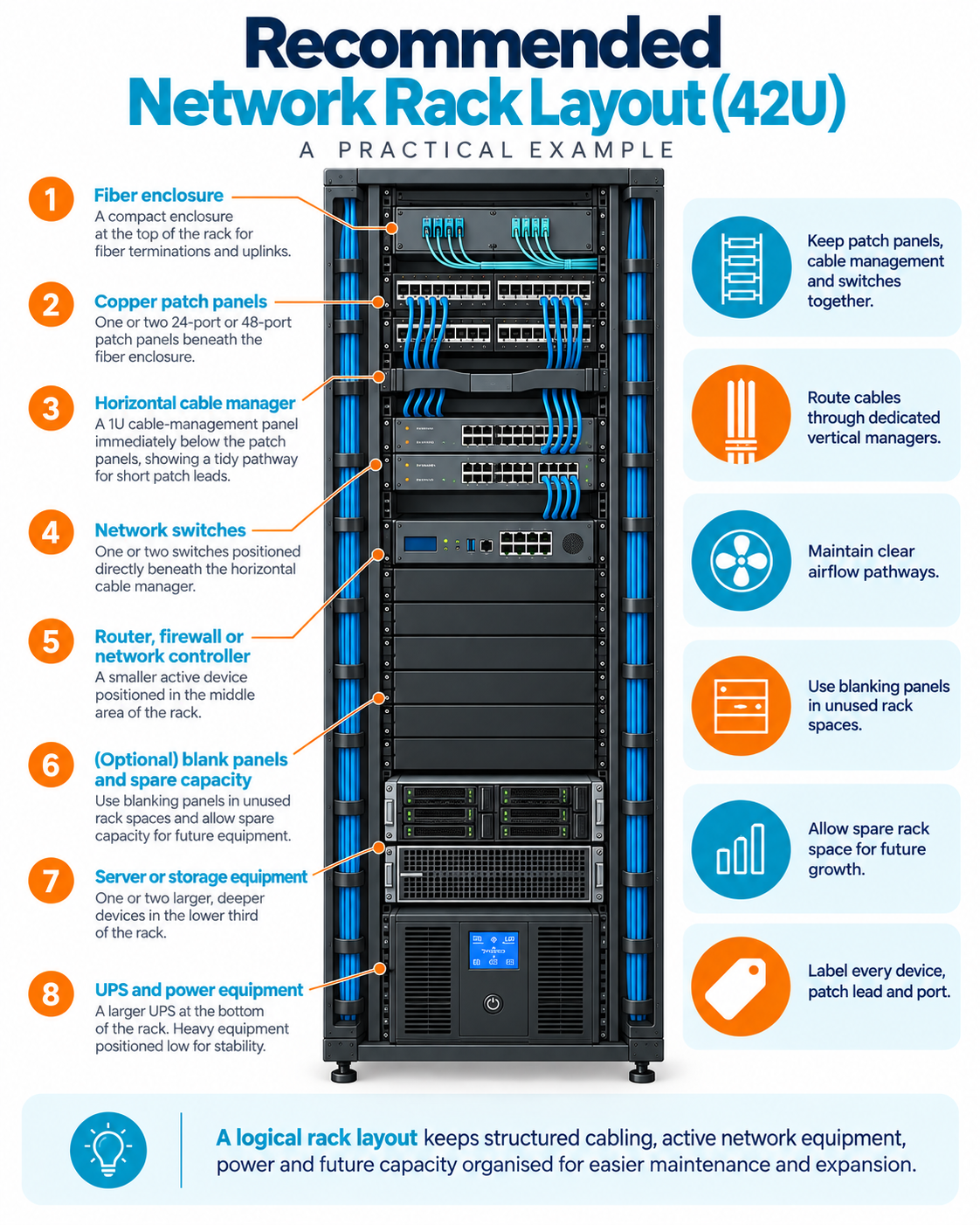
Rack Position | Typical Equipment | Why it Works |
|---|---|---|
Upper Rack | Fiber enclosures and copper patch panels | Supports clean entry and termination of structured cabling |
Beneath patch panels | Horizontal cable managers | Provides a controlled pathway for patch leads |
Central area | Network switches | Keeps switch ports close to corresponding patch panel ports |
Mid-to-lower rack | Firewalls, routers, controllers, NVRs and lighter servers | Keeps regularly serviced equipment accessible |
Lower rack | Heavier servers, storage and chassis equipment | Improves weight distribution and rack stability |
Bottom | UPS units and large power equipment | Places the heaviest components at the most stable point |
Design for Airflow, Power and Access
Performance and equipment lifespan depend on more than network configuration. Heat, power capacity and physical access need to be considered as part of the layout.
Protect the Airflow Path
Most active network and server equipment is designed around a defined airflow direction. Before mounting devices, check whether they draw air from front to back, side to side, or use another configuration. A rack that blocks intake or exhaust vents can create heat pockets, reduce equipment efficiency and increase the risk of premature hardware failure.
Good airflow practices include:
- Keep cable bundles out of the central airflow path.
- Use vertical cable management systems at the sides of the rack where possible.
- Install blanking panels in unused rack spaces to reduce recirculation between hot exhaust air and cool intake air.
- Avoid tightly packing devices where ventilation is limited.
- Ensure there is adequate clearance around the rack, especially at rear doors and exhaust points.
- Consider fan trays, temperature sensors or more substantial cooling solutions where power-dense PoE switches, servers or storage equipment are installed.
Place Power Strategically
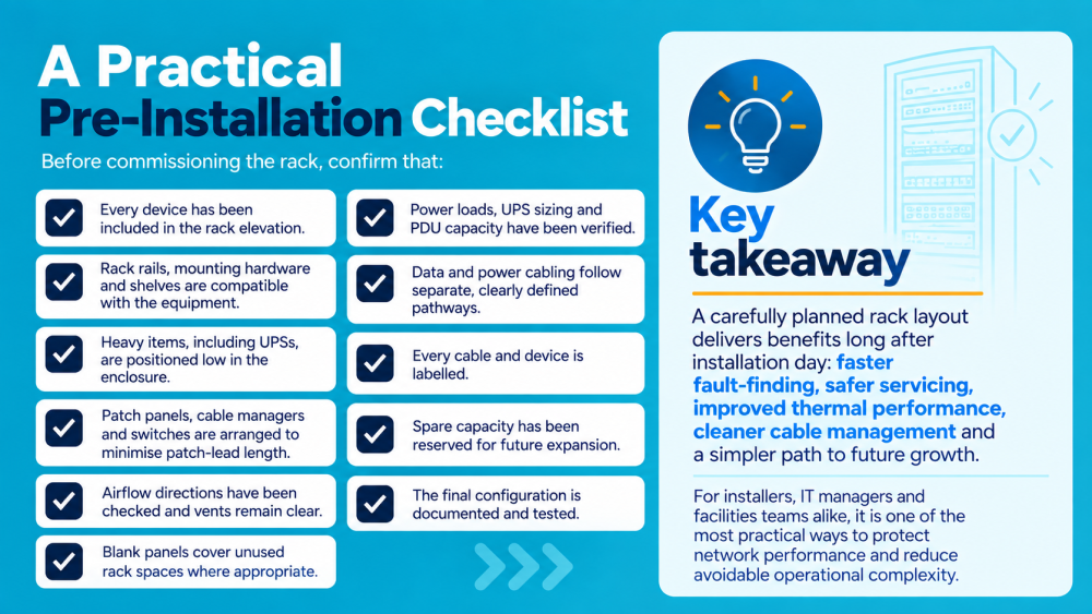
Power should be designed before cables are dressed—not treated as an afterthought. Confirm the total expected load, UPS runtime requirements, PDU capacity, socket types and any redundancy needs before finalising the rack elevation.
For critical infrastructure, consider separate power paths and PDUs where the installed devices support dual power supplies.
Position PDUs so that power leads can reach equipment without stretching across the front of the rack or obstructing network cabling. Avoid daisy-chaining power boards; use properly rated rack-mounted distribution equipment instead.
A UPS is usually best mounted at the bottom of the rack because of its weight. Leave enough room around it for maintenance, battery replacement and ventilation.
Make Maintenance Easy
An attractive rack layout is useful—but serviceability is the real measure of success. Frequently accessed devices should be mounted at a practical working height, with port labels visible and clear access to front and rear connections.
Before final installation, confirm:
- Front and rear doors can close without compressing cables.
- Rails support the depth and weight of every device.
- Equipment can be removed or replaced without dismantling adjacent infrastructure.
- Patch cables have sufficient slack for service, but not so much that they become tangled. Doors, fans and ventilation openings remain unobstructed.
Treat Cable Management as Infrastructure
Cable management affects reliability, troubleshooting time and the ability to grow the network cleanly. A crowded rack may still function, but it becomes harder to identify faults, replace equipment and preserve airflow.
Use horizontal managers between patch panels and switches, and vertical managers for larger cable bundles travelling up or down the rack. Choose patch leads that are long enough to follow the intended route without strain, but short enough to avoid loops and excess congestion.
A disciplined approach includes:
- Label both ends of every cable with a meaningful, unique identifier.
- Apply a consistent colour system—for example, different colours for user data, uplinks, voice, CCTV, wireless access points or management connections.
- Keep mains power and data cabling separated where practical.
- Use hook-and-loop fasteners rather than overtightened cable ties, particularly for copper and fiber cabling.
- Maintain bend-radius requirements, especially for fiber and higher-category copper cable.
- Remove abandoned patch leads and redundant equipment during routine audits.
- Record each cable route, port assignment, device name and rack position in the network documentation.

Plan for Growth from Day One
A network rack should accommodate the organisation you expect to become, not simply the equipment currently on the purchase order. This is especially important as demands increase for wireless access points, IP surveillance, access control, AV-over-IP, cloud connectivity and PoE-powered devices.
When planning for growth, allow for:
- Spare rack units and shelf capacity
- Unused patch-panel port
- Extra switch capacity or a planned switch-expansion path
- Available PoE budget for future devices
- Adequate PDU capacity and UPS headroom
- Space in vertical cable managers and cable pathways
- Sufficient rack depth for later equipment upgrades
- Cooling capacity for a higher-density configuration
Document the final layout as a rack elevation, showing each device’s rack position, model, serial number, power source, uplink and management details. Keep this record current whenever equipment is added, removed or moved. Accurate documentation turns a future upgrade from a time-consuming investigation into a planned task.
Build Your Rack with the Right Components
Good rack planning is only part of the equation. The right combination of patch panels, cable management, and patch cords helps turn a well-planned rack layout into a clean, serviceable installation.
Patch Panels
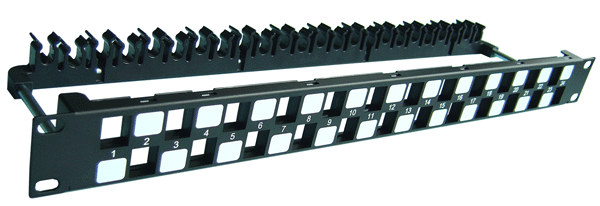
PowerMAX+ 1U 24P Cat.6/6A UTP Snap-in Panel
Cable Management
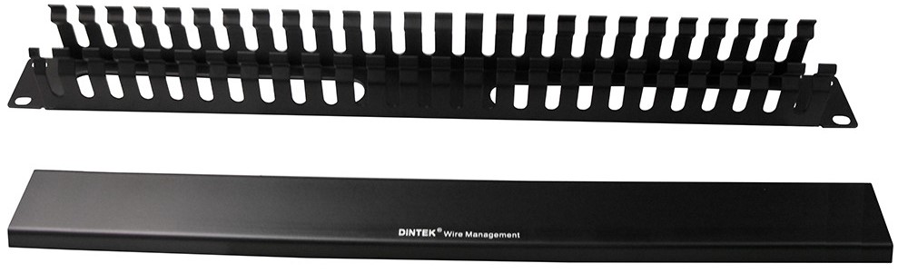
1U Single Sided Metallic Finger Duct Panel With Front Cover
Patch Cords
PowerMAX+ 1U 24P Cat.6/6A UTP Snap-in Panel
Patch panels provide an organised interface between structured cabling and active network equipment, making connections easier to identify, manage and change.
DINTEK offers copper patch panel solutions for different network requirements, including modular and high-density configurations.
Effective cable management creates defined pathways for patch leads and cable bundles, helping reduce congestion, maintain bend radii and keep connections accessible.
DINTEK's cable management solutions are designed to support clean, organised rack installations.
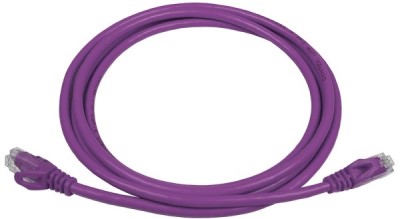
The right patch cords help create short, tidy connections between patch panels, switches and other network equipment.
DINTEK offers a range of patch cords in different lengths and colours, supporting both practical cable management and consistent colour-coding systems.